Level Sensors & Switches

LS-750 Single-Point Level Switch

Part Number: 149350
LS-750_197433
Image is of similar product

PRODUCT DESCRIPTION:

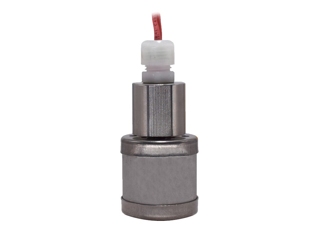
LS-750 Series Single-Point Level Switch units are ideal for use in oils and water. With a compact-sized float, slosh shield and weighted collar, the LS-750 provides liquid level detection for a wide variety of applications. Suspend in stand pipes or sumps for leak detection duty or drop into wells for ground-water monitoring. Supplied with 25 feet (7.62 m) of waterproof cable.

  • Ideal for Use in Oils and Water
  • Slosh Shield
  • Supplied with Waterproof Cable
CE ROHS Gems Compliant CSA

Features

  • Ideal for Use in Oils and Water
  • Slosh Shield
  • Supplied with Waterproof Cable
SKU
149350
Model
LS-750
Sensor Type
Float Type
Primary Material Of Construction
Alloy
Wetted Materials
Brass, Buna N, Nylon, PVC, Berylium Copper
Stem Material
Brass
Float Material
Buna N
Float Diameter
1"
Actuation Level
3/4"
Min. Liquid SG
0.45
Maximum Pressure
150 psi
Minimum Temperature
-40°F
Maximum Temperature
230°F
Mounting Size
Bracket
Mounting Style
Vertical
Electrical Termination
25' Long, 22 AWG, (2) Conductor PVC Cable
Switch Type
SPST (20 VA)
Switch Operation
Normally Closed (Non-Reversible)
Input
N/A
Output
N/A
Approvals
UL Recognized, CSA Listed, CE

Reed Switch Protection

Format .pdf
Size 56 KB

Gems Sensors Instructions, LS-750

Format .pdf
Size 124 KB

Gems Sensors Catalog, Specialty Switches

Format .pdf
Size 4 MB
What is the life expectancy of a reed switch?

A reed switch is extremely rugged and designed to operate reliably for many years, under ideal conditions, up to about 2 million cycles. To achieve maximum service life, reed switches benefit from protected electrical supply. 

Will different liquid media affect the time delay for optic sensors?

If the viscosity is similar, the time delay should be the same for different media.

After programming my Ultrasonic Sensor, the output constantly reads 4mA, what should I do?

Recalibrate the sensor. The sensor reads to the 1/10 of an inch and the decimal point is easy to miss. It is possible to calibrate the unit to one distance and actually be at another distance. Example: 123" is 12.3" and NOT 123". If EC4 is entered as 100 and EC20 at 25, the sensor assumes the range to be from 10.0" to 2.5". Any distance over 10.0" would then read 4mA.

What is the standard thread callout for the mating connector on the LS-700 model type with optional pin connection?

It is ½-20 UNF-2A Reference.

What is the mating cable connector for a standard custom made LS-700 model type with a 5 pin connection?

Web search Brad Harrison series 705000. Example: Brad Harrison part# 705000D02F060 is for a single ended straight 6ft length

What is the mating cable connector for a standard custom made LS-700 model type with a 4 pin connection?

Web search Brad Harrison series 704000. Example: Brad Harrison part# 704000D02F060 is for a single ended straight 6ft length

What is the mating cable connector for a standard custom made LS-700 model type with a 3 pin connection?

Web search Brad Harrison series 703000. Example: Brad Harrison part# 703000D02F060 is for a single ended straight 6ft length

What is the mating cable connector for a standard custom made LS-700 model type with a 2 pin connection?

Web search Brad Harrison series 702000. Example: Brad Harrison part# 702000D02F060 is for a single ended straight 6ft length.

What is the diode part number that is referenced for inductive loads per the wiring diagram for an Optic sensor?

Reference Diode part# 1N4004, (400V peak input voltage)

Is there a preferred mounting position for the ELS-1150 and ELS-1150XP Optical sensor?

These sensors must be mounted horizontally or up to 45 degrees from horizontal only. Reason, possible drips on tip can cause false indication. Also do not want to create air pockets.

Does Gems offer an optic sensor with a time delay?

For large volume OEM applications, a custom time delay is available on the programmable microprocessor version of the ELS-1150, which can be programmed for on, off or both delays from 2 seconds to 255 seconds. All delays have a ±1 second tolerance. Call Gems for more information.

What is the mating connector for part# 144900?

Mating Plug Amp # 206060-1

What is the mating connector for part #128500?

Mating Plug Brad Harrison 70303 series.

How do I wire part# 181291, model type LS-7 with 5 AMP relay?

Please see the wiring diagram below: Wire diagram for part 181291

Can you connect more than one 12 volt Sinking Electro Optic Sensor to the Opto Pak Controller?

The Opto-Pak controller was designed for just one relay output. However, when using 12 VDC Electro Optics in parallel with one Opto-Pak controller Part# 149536 or 149535 with Nema4X Enclosure, the following is possible: Maximum capability: 100Ma Maximum optic sensors: 4 For multiple sensors wired in parallel to one Opto pak Controller, the sensors will exhibit logical OR operation: Dry Sink sensors: if any sensor is dry, the Opto Pak Controller relay will be energized, and all sensors would have to be wet to de-energize the relay. Wet Sink sensors: if any sensor is wet, the Opto Pak Controller relay will be energized, and all sensors would have to be dry to de-energize the relay.

What is the difference between "sinking" and "sourcing?"

Sinking and sourcing are terms used to describe how an associated load (the device being turned on or off by the sensor) is powered in relation to the sensor. Sinking, the more widely used of the two, involves the switching of load current (power) supplied by a power source external to the sensor. In a sinking configuration, current passes through the load first, through the output switch of the sensor second and lastly to ground. A sensor with a sinking output switches the ground, or negative, leg of the circuit. In contrast, sourcing refers to a configuration in which the sensor is the source of the current required to power the load. In a sourcing situation, current supplied by the sensor passes through the load second and then to ground. A sensor with a sourcing output switches the positive leg of the circuit.

What is meant by "CMOS/TTL logic?"

TTL stands for Transistor-Transitor Logic and is considered a logic family. A logic family is a collection of different IC chips that have similar input, output and internal circuit characteristics, but that perform different logic functions. CMOS, which stands for Complementary Metal-Oxide Semiconductor, is another type of transistor logic family that has become more popular than TTL in recent years thanks to higher speed and lower power consumption (e.g. the 0.5 mA associated with the CLS-1200's 5 VDC output option is sufficient to drive only one TTL logic gate versus ten CMOS gates). The majority of today's large-scale ICs, such as microprocessors, use CMOS.