SEARCH OUR RESOURCE CENTER
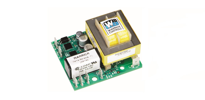

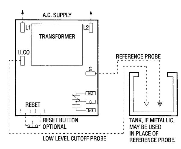
The Series 26 liquid level controller is an open circuit board design with spade terminals for use with float-type or conductive probe-type level sensors. It is designed for low-water cutoff protection.

Sensitivity
How sensitive does the control module need to be? The general rule is the sensitivity of the control (e.g. 10K, 26K etc.) should be greater than the resistance of the liquid. The less conductive (more resistance) a liquid is, the more sensitive the control module needs to be. It is usually better to choose the sensitivity level that is above, yet as close to the conductivity/resistance as you can. Choosing a level too high could sense mist, foam, steam, etc., or even cause the module to not operate properly. Gems has offered a conductivity chart HERE . In some applications the wire distance from probe to control module needs to be factored in, and that guide is found HERE . Please note, if your liquid conductivity is too high for any sensitivity level listed, then you will need to consider a float-type level sensor.
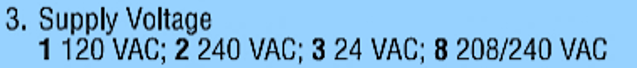
Supply Voltage
The supply voltage selection is what is used to power the control module (attached to terminals L1 and L2).

Standoff Style
Standoffs are what secure the control module to your existing panel.
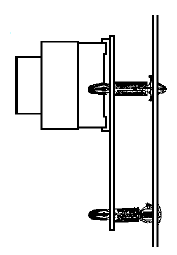
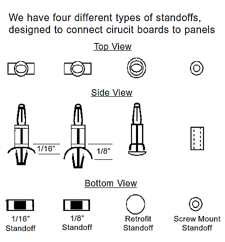
The retrofit standoffs are used when replacing the obsolete Warrick Series 1 control module with a new Series 26 (paired with retrofit plate option from Chart with section 6).

Enclosure
You can choose to have the control module affixed within a 6x6x4 fiberglass NEMA rated enclosure.
Type 1 enclosure constructed for indoor use to provide a degree of protection to personnel against access to hazardous parts and to provide a degree of protection of the equipment inside the enclosure against ingress of solid foreign objects (falling dirt).
Type 4 offered is type 4X enclosure constructed for either indoor or outdoor use to provide a degree of protection to personnel against access to hazardous parts; to provide a degree of protection of the equipment inside the enclosure against ingress of solid foreign objects (windblown dust); to provide a degree of protection with respect to harmful effects on the equipment due to the ingress of water (rain, sleet, snow, splashing water, and hose directed water); that provides an additional level of protection against corrosion; and that will be undamaged by the external formation of ice on the enclosure.

Option Package
Detailed options descriptions can be found in the instructions document found HERE .
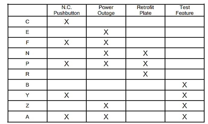
Note: Retrofit option required when replacing obsolete Warrick Series 1 control module (paired with D-type retrofit standoffs).

Time Delay
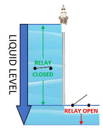
The time delay option can be used to prevent excessive relay operation due to waves, turbulence, disruptions in the water level when at or near the probe end. With time delay on increasing level, the liquid must be in contact with the low-level cutoff (LLCO) electrode for the full duration of the time delay before control will operate. 3 Second time delay on decreasing level is standard. Delay up to 90 seconds can be specified and would act in the same manner as listed above.