 SEARCH OUR RESOURCE CENTER
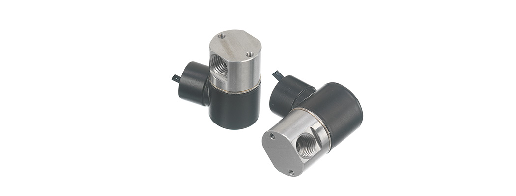
Gems Sensors manufactures solenoid valves in various types of configurations. For example, 2-Way normally closed, 2-way normally open, 3-way normally closed, 3-way normally open etc. The below diagrams help explain the flow paths of each to help selecting the right configuration for your application.
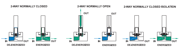
2-Way Solenoid Valve Configurations
The most common and simple to understand are 2-way configurations. They have an inlet and an outlet, hence 2-way. For valves, they are either open or closed, and with solenoid valves current needs to be applied to them to actuate. The blue indicates when the valve is closed, blocking flow. The green indicates when the valve is open, allowing flow.
For 2-way normally closed when no power is applied, the valve is closed. For 2-way normally open, when no power is applied, the valve is open. So, it depends on the application and whether the valve may be open most of the time or closed most of the time. It’s important to think about the failure modes as well. If power is lost, on a 2-way normally closed the valve will close. That may be good for some applications but bad for other applications where they don’t want pressure stored. On a 2-way normally open valve, if power is lost the valve will remain open and may be beneficial as it won’t store any pressure.
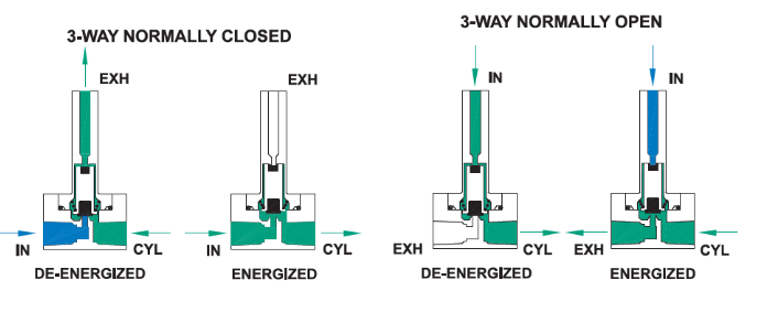
3-Way Solenoid Valve Configurations
For 3-way valves, there are an inlet, an outlet, and an exhaust, hence 3-way. The below show the difference between a 3-way normally closed, and a 3-way normally open. Typical applications for 3-way valves are pneumatic cylinders and pilot valves, where the air needs a port to exhaust to the atmosphere.
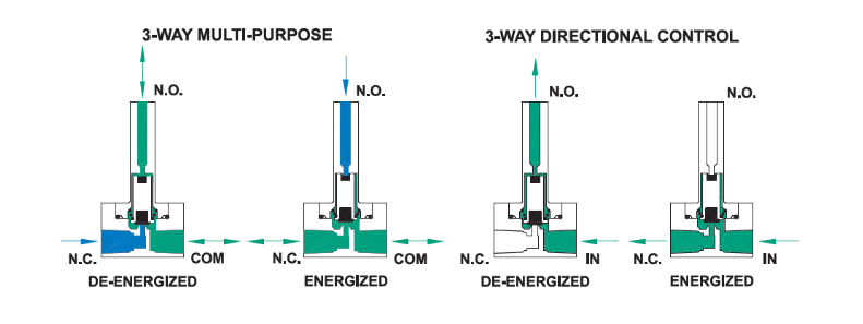
Two other 3-way valves are multi-purpose, and directional control. The below diagrams show the difference in flow paths. These allow for flow to be directed to one port or the other and allow for flow to travel in either direction.
Learn more about Solenoid Valve options HERE