 SEARCH OUR RESOURCE CENTER
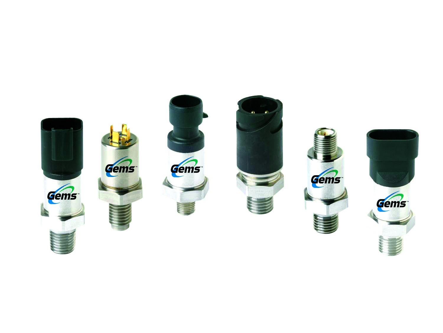
When you are troubleshooting an issue with your sensor or device, we recommend completely removing it from your system to bench test it. Many times, the customer’s wiring/PLC/controller can incorrectly influence the testing circuit and adds variables to your testing. The method below reduces as many variables as possible to ensure that your sensor is working OK. If there is an error in the wiring or controllers, this will attempt to remove them from the equation.
1. Preparation:
a. Remove the sensor from your system completely.
i. If that is not possible, then only electrically remove it from the system.
b. Make sure your power supply and multimeter are off.
c. Download the 3100 Series bulletin here for reference:
/search-products/product-details/3100-3200-series-pressure-transducers-
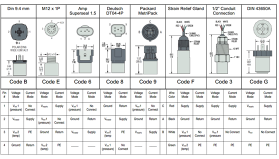
Reference the pinout chart for the two pins/wires used in the 4-20 mA output:
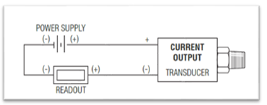
2. Basic wiring diagram:
See below.
3. Components for the Bench Test:
a. Known good Power Supply, capable of producing 8 to 30VDC.
i. 24VDC is an average input voltage but not required.
b. Known good Multimeter, set to measure milliamps (READOUT).
c. Appropriate mating electrical connectors (if needed).
4. Wiring your Bench Test Setup:
a. From your Power Supply, connect a wire from the (+/RED) connection to the SUPPLY input of your sensor.
b. From the (-/BLACK) connection of the Power Supply, connect a wire to the (-/BLACK) connection of your handheld ammeter (READOUT).
c. From the (+/RED) side of your Ammeter, connect a wire to the RETURN connection of the sensor.
d. Do not connect anything to the other wires/pins of your sensor.
5. Gotcha’s:
a. Make sure you have NOTHING else connected to this circuit. This will eliminate any variables in the test.
b. Make sure your Multimeter is set to MILLIAMPS (or AMPS). Not Volts or Ohms.
c. Make sure your probes are in the correct holes of the Multimeter to read AMPS or MILLIAMPS. Some meters have one connection for amps and one connection for volts/ohms.
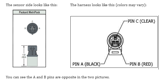
d. If you are using a mating connector, pay attention to the Pin callouts.
They are opposite on the sensor versus the harness so when you connect them, they line up correctly.
i. For example, the Packard pinouts:
6. You are now ready to start the BASIC Bench Test:
This will give you a simple health check of the sensor to make sure it has an output.
a. Double check all wiring.
b. Turn on the Multimeter, set to the MILLIAMP range if possible.
c. Turn on your Power Supply. If you can, set it to 24 VDC.
d. With no pressure on the sensing port of the sensor, you should see 4 mA (or 0.004 A) plus or minus a small error Zero Tolerance error. The Zero Tolerance error spec for the 3100 is 0.5% of Span. Span is 16 mA (20 mA less 4 mA).
e. If you see any output that is greater than 4.08 mA or less than 3.92 mA, you might have a bad sensor. If it is in that range, then you are OK.
f. Turn off the Power Supply and Multimeter.
7. If you have a pressure source available, you can perform the ADVANCED Bench Test:
This will allow you to check the sensor at pressure.
a. Connect to a known reliable and accurate pressure source.
Be careful when high pressure is involved.
b. Turn on the Multimeter.
c. Turn on your Power Supply.
i. If you can, set it at 24 VDC.
d. Repeats Step 6 above: With no pressure on the sensing port of the sensor, record the Ammeter reading. This is your Zero Point value.
e. Apply the appropriate maximum measuring pressure for your sensor. This will be labeled as RANGE on the sensor.
Note the value on your Multimeter and record it. This is your Max Point Value.
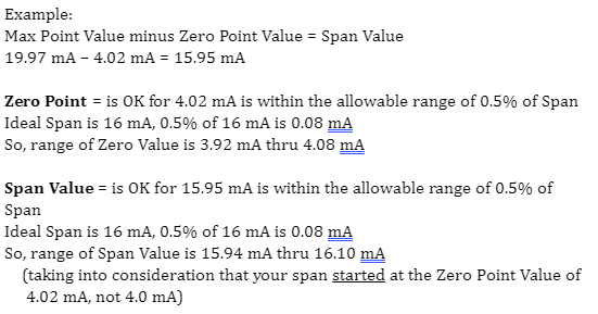
f. To calculate if the sensor is operating correctly, use this formula:
i. Max Point Value minus Zero Point Value = Span Value
g. Turn off the Power Supply and Multimeter and disconnect all your wiring.